INFINITY TURBINE LLC We specialize in designs, plans, licensing, consulting, design services, and surplus spare parts. We no longer manufacture turbines or CO2 systems. More Info...
TEL: +1-608-238-6001 (Chicago Time Zone ) USA
Email: greg@infinityturbine.com
CO2 Ejectors for Data Center Waste Heat Cooling: A Technical Review Hyperscalers are racing to deploy gigawatts of AI compute, but the grid can't keep up and large gas turbines are backordered half a decade out. Infinity Turbine's Cluster Mesh Supercritical CO₂ system offers a radical alternative: modular, silent, trailer-deployable prime power that scales the way software does... More Info
Turning AI Data Center Waste Heat Into Electricity More Info
Cooling a Data Center Pod with Its Own Waste Heat: A 100 kW Ejector Design Study More Info
Portable Gas Turbine Prime Power AI data centers are pushing electrical infrastructure to its limits. The traditional AC power chain is no longer optimal for GPU-driven workloads. A DC-native architecture using Infinity Turbine’s Cluster Mesh system offers a path to higher efficiency, lower costs, and scalable modular power—potentially saving tens of millions per year at hyperscale... More Info
SMR and Cluster Mesh Supercritical CO2 Power System for Data Centers and AI Pairing Cluster Mesh Supercritical CO2 Power System with Small Modular Reactors enables hyperscalers to convert high-grade nuclear heat into ultra-efficient, dispatchable power with a compact, modular footprint tailored for AI-scale demand. More Info
ORC and Products Index Infinity Turbine ORC Index... More Info
AMD Helios Cooling Strategy Using Transcritical CO2 and a Cluster Mesh sCO2 Turbine Generator Cell More Info
|
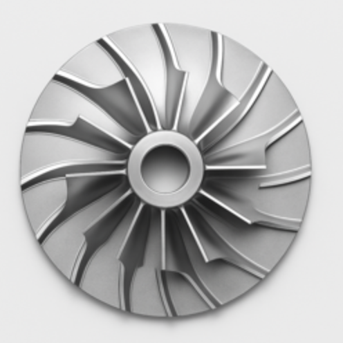
Supercritical Turbine Rotor Design Rotor body: single flat disc, thickness t.Blades: cut into the disc as planar wedge airfoils with constant thickness (or 2.5D engraving if you want a slight leading-edge radius).Geometry: all variation is in-plane (no 3D lean, sweep, or thickness stacking).Trade-offs: lower diffusion capability and higher loss vs. 3D impellers. Aim for pressure ratio per stage ~1.25–1.5 and keep tip Mach moderate.Baseline design targets for sCO₂ (flat rotor)Overall pressure ratio per stage: 1.25–1.5Flow coefficient φ = Vm2/U2: 0.07–0.10Loading coefficient ψ = Δh/U2²: 0.45–0.60Slip factor σ: ~0.88–0.92 (backswept)Exit metal angle β2 (relative): 25–35 degBending safety: t typically 3–8 mm for small rotors; verify with stress calcs.Rotational layout1. Pick hub and tip radii: R1e (eye inlet), R2 (impeller tip).2. Choose blade count Z such that pitch-to-thickness avoids blockage: solidity at mid-span S = chord/pitch ~0.8–1.2.3. Set inlet metal angle β1 = atan(Vm1/U1) (for zero prewhirl), and exit metal angle β2 backswept 25–35 deg.4. Use a logarithmic-spiral camber line from near-radial at the inlet to backswept at the exit.Blade outline you can machine from a flat plate1) Camber line as a logarithmic spiralUse polar coordinates with the rotor center as origin.Spiral: r(θ) = r₂ · exp[a·(θ − θ₂)]Set the spiral tangent angle at exit equal to your backsweep: α_exit = 90° − β2.For a log spiral, the tangent angle is constant and equals arctan(1/a).So choose a = 1 / tan(α_exit).Define the blade from θ = θ₁ at r = r₁ (near inlet radius) to θ = θ₂ at r = r₂ (impeller tip).2) Thickness distribution (constant or simple airfoil)Easiest: constant thickness t_b with rounded leading edge radius ~0.05·t_b.Slightly better: a simple “pseudo-airfoil” thickness:Half-thickness h(s) = t_max · 4·s·(1 − s), where s runs 0→1 along the camber length.Create the pressure and suction edges by offsetting the camber line ±h(s) normal to the camber at each point.3) Blade count and pitchAt radius r, pitch p = 2πr / Z.Keep local solidity S = chord_normal_to_cam/p near 1 at mid-span to avoid over-diffusion.Quick FileMaker-friendly point generator (returns XY points)This generates a 2D blade polygon: camber via log spiral plus symmetric thickness. You can export the resulting points to CSV and import into CAD to make a DXF profile.```Let ([/ Inputs you set as fields or globals /R1 = R1_inlet_m;R2 = R2_tip_m;Z = BladeCount;beta2_deg = ExitMetalAngle_deg; / e.g. 30 /tmax = BladeMaxThickness_m; / e.g. 0.002 /npts = 100; / points along camber // Derived spiral parameter for backsweep /alpha_exit_deg = 90 • beta2_deg;alpha = alpha_exit_deg Pi / 180;a = 1 / Tan( alpha );/ Start angle so that r(R1) matches the spiral at entrance /theta2 = 0; / choose tip at theta2 = 0 /theta1 = theta2 • ( 1/a ) Ln( R2 / R1 );/ Build point list along camber and offset for thickness /i = 0;/ Accumulator for points as text lines: X Y /points```Page TitleFlat-Plate Centrifugal Compressor Bucket for sCO2: A 2D Laser-Cut Design You Can CAM TodayMeta DescriptionYes, you can build a centrifugal compressor rotor for supercritical CO2 from a flat plate. This article explains the tradeoffs, the recommended 2D blade geometry using a logarithmic spiral, and gives FileMaker-ready code to generate blade coordinates from temperature, pressure, RPM, pressure ratio, and your chosen rotor size.Can a 2D, flat-plate compressor wheel work for sCO2?Yes, with caveats. A conventional high-efficiency centrifugal impeller uses 3D blade sweep and twist to control incidence, Mach, and diffusion from hub to shroud. If you constrain yourself to a flat plate impeller with 2D blades:It will work, especially for small sCO2 machines where diameters are modest and the fluid is dense.Expect lower peak efficiency and a narrower surge margin versus a 3D impeller.Keep backsweep at the exit and modest flow coefficient to avoid high relative Mach and separation.The best 2D compromise is a backswept, constant-thickness blade whose camber line follows a logarithmic spiral. This gives a constant metal angle relative to the local radius, which is compatible with the quasi-2D velocity triangles of a radial compressor.What to choose before you cut metalTie these to the sCO2 design point you already sized (from your earlier compressor calcs):D2_m: impeller tip diameter from your head and RPM.R1_m: inlet eye radius at the blade start. Use your eye tip diameter D1_tip from the Mach-limited inlet sizing.beta_deg: target exit blade metal angle relative to the tangent (backswept). Typical 2D values for dense sCO2: 50 to 70 degrees.Zb: blade count. Start with 12 to 16 for small rotors.phi: flow coefficient at exit, keep 0.06 to 0.10 for a cautious 2D design.t_mm: physical blade thickness to leave after cutting or milling. For a 2D plate, 1.5 to 3.0 mm is typical at small diameters.npts: number of points along the blade centerline to export for CAM, e.g. 200.Note on angle convention: beta_deg here is the blade metal angle at the exit, measured from the circumferential (tangential) direction. Backswept means beta_deg is a large angle (e.g., 60 deg), not radial.Geometry choice: the logarithmic spiralA blade camber line defined by a logarithmic spiral maintains a constant angle between the blade tangent and the local radius. That constant angle is your chosen blade metal angle beta_deg.In polar form:r goes from R1_m to R2_m = D2_m / 2theta(r) = theta0 + k ln(r / R1_m)with k = cot(beta_rad), where beta_rad = beta_deg pi / 180The curve is then converted to XY for your CAM or laser.For a flat plate, you can:Machine or laser the centerline curve, then offset the toolpath by t_mm/2 to both sides in your CAM, orExport two curves by shifting theta slightly at each radius to approximate constant thickness along the tangent. The simplest is to export the centerline and let CAM handle the offset.Manufacturing and performance tipsUse a shroud if possible to control tip leakage.Add a small leading-edge radius (0.2 to 0.5 mm) to soften incidence.Keep surface finish smooth; sCO2 is dense and losses scale with roughness.Start conservative on pressure ratio per stage; add a second stage if needed.Validate with a static pressure tap at diffuser entry and monitor surge.FileMaker Pro generator for a 2D blade centerlineThis FileMaker calculation returns a CSV list of X,Y points for one blade centerline from R1_m to R2_m, plus rotated copies for the full blade count Zb. Paste into a Calculation field and output the result to a text field for DXF import or straight to CAM.Inputs you provide as fields or globalsD2_m tip diameter in metersR1_m inlet radius where the blade begins, metersbeta_deg blade metal angle at exit relative to tangent, degreesZb number of bladesnpts number of points along the bladetheta0_deg starting angular index for blade 0, degrees, e.g. 0t_mm blade thickness in millimeters if you want to offset later in CAMYou may also include your thermodynamic sizing in the same record to document T1, P1, PR, N_rpm; they do not enter the pure geometry below.```Let([pi = 3.14159265358979;D2 = D2_m;R1 = R1_m;R2 = D2 / 2;beta = beta_deg;Z = Zb;Npts = npts;theta0 = theta0_deg;// Log spiral parameter: k = cot(beta)beta_rad = beta pi / 180;k = Cos(beta_rad) / Sin(beta_rad);// Build centerline points for one blade in polar, then to XY// r_i = R1 (R2/R1)^(i/(Npts-1))// theta_i = theta0 + k ln(r_i / R1) in radians// Convert to degrees for FileMaker trigMakePoint =Let([i = GetAsNumber( GetValue ( $$i ; 1 ) );r = R1 Power( R2 / R1 ; i / (Npts • 1) );theta_rad = (theta0 pi / 180) + k Ln( r / R1 );theta_deg = theta_rad 180 / pi;x = r Cos( theta_deg );y = r Sin( theta_deg )];List( x ; y ));// Generate points for blade 0PointsOneBlade =Let([$$i = 0;acc = ;j = 0];While (j < Npts ;$$i = j ;acc = List( acc ; Evaluate( MakePoint ) ) ;j = j + 1);acc);// Rotate the one-blade list to create Z blades// Rotation angle per blade = 360 / Zrot_step = 360 / Z;RotatePoint =Let([x0 = GetAsNumber( GetValue( ~pt ; 1 ) );y0 = GetAsNumber( GetValue( ~pt ; 2 ) );ang = rot_deg pi / 180;xr = x0 Cos( rot_deg ) • y0 Sin( rot_deg );yr = x0 Sin( rot_deg ) + y0 Cos( rot_deg )];List( xr ; yr ));// Assemble CSV text: blade,index,x,yBuildCSV =Let([b = 0;csv =];While (b < Z ;Let([rot_deg = b rot_step;row = 1;bladeCSV = ;countPts = ValueCount( PointsOneBlade )];While (row <= countPts ;~pt = GetValue( PointsOneBlade ; row );xy = Evaluate( Substitute( RotatePoint ; rot_deg ; rot_deg ) );x = GetValue( xy ; 1 );y = GetValue( xy ; 2 );bladeCSV = List( bladeCSV ; b & , & row & , & x & , & y );row = row + 1);csv = List( csv ; bladeCSV );b = b + 1);csv)];Substitute( BuildCSV ; Char(13) ; Char(10) ))```What you getA CSV where each line is`blade_index,point_index,x_meters,y_meters`Import to CAD, generate offsets of plus or minus t_mm/2000 meters to produce the two cut paths around the centerline, or simply CAM-offset by half the desired thickness.How to choose beta and R1 quickly from your sCO2 pointIf your earlier compressor sizing gave exit metal angle beta2_deg and eye diameter D1_tip, reuse those.Set beta_deg = beta2_deg.Set R1_m = D1_tip / 2.Keep Zb such that the solidity at mid-span is about 1 to 1.5 for a 2D plate. If your blade spacing at radius r is s = 2 pi r / Zb, target chord c roughly similar to s to keep diffusion gentle.Expected performance vs a 3D impellerPeak adiabatic efficiency typically 3 to 8 points lower than a well-designed 3D impeller.Slightly higher noise and narrower stable flow range.For dense sCO2 with modest pressure ratio per stage, the penalty is often acceptable for rapid prototyping or low-cost builds.Next steps1. Run the FileMaker calc to generate the CSV, import to CAD, and offset for thickness.2. Waterjet or laser the blank and finish with a light deburr and leading-edge radius.3. Pair with a simple vaneless diffuser of width about 8 to 12 percent of D2 and radius ratio 1.2 to 1.4 as a starting point.4. Test with conservative pressure ratio, log static at diffuser inlet, iterate beta and Zb as needed.This approach lets you go from your sCO2 design point to a cuttable, 2D impeller in a single session, accepting known tradeoffs while keeping the geometry manufacturable by flat-plate methods.-----Let([pi = 3.14159265358979;D2 = D2_m;R1 = R1_m;R2 = D2 / 2;beta = beta_deg;Z = Zb;Npts = npts;theta0 = theta0_deg;// Log spiral parameter: k = cot(beta)beta_rad = beta * pi / 180;k = Cos(beta_rad) / Sin(beta_rad);// Build centerline points for one blade in polar, then to XY// r_i = R1 * (R2/R1)^(i/(Npts-1))// theta_i = theta0 + k * ln(r_i / R1) in radians// Convert to degrees for FileMaker trigMakePoint ="Let([i = GetAsNumber( GetValue ( $$i ; 1 ) );r = R1 * Power( R2 / R1 ; i / (Npts - 1) );theta_rad = (theta0 * pi / 180) + k * Ln( r / R1 );theta_deg = theta_rad * 180 / pi;x = r * Cos( theta_deg );y = r * Sin( theta_deg )];List( x ; y ))";// Generate points for blade 0PointsOneBlade =Let([$$i = "0";acc = "";j = 0];While (j < Npts ;$$i = j ;acc = List( acc ; Evaluate( MakePoint ) ) ;j = j + 1);acc);// Rotate the one-blade list to create Z blades// Rotation angle per blade = 360 / Zrot_step = 360 / Z;RotatePoint ="Let([x0 = GetAsNumber( GetValue( ~pt ; 1 ) );y0 = GetAsNumber( GetValue( ~pt ; 2 ) );ang = rot_deg * pi / 180;xr = x0 * Cos( rot_deg ) - y0 * Sin( rot_deg );yr = x0 * Sin( rot_deg ) + y0 * Cos( rot_deg )];List( xr ; yr ))";// Assemble CSV text: blade,index,x,yBuildCSV =Let([b = 0;csv = ""];While (b < Z ;Let([rot_deg = b * rot_step;row = 1;bladeCSV = "";countPts = ValueCount( PointsOneBlade )];While (row <= countPts ;~pt = GetValue( PointsOneBlade ; row );xy = Evaluate( Substitute( RotatePoint ; "rot_deg" ; rot_deg ) );x = GetValue( xy ; 1 );y = GetValue( xy ; 2 );bladeCSV = List( bladeCSV ; b & "," & row & "," & x & "," & y );row = row + 1);csv = List( csv ; bladeCSV );b = b + 1);csv)];Substitute( BuildCSV ; Char(13) ; Char(10) ))
|
| OverviewYou can build a 2D, flat-plate radial-inflow turbine for supercritical CO2 (sCO2) as a fast, low-cost prototype. Performance will be below that of a fully 3D radial turbine, but for moderate pressure ratio and dense sCO2 it is practical. The strategy mirrors the 2D compressor approach: use a logarithmic-spiral camber line that maintains a constant metal angle, keep relative Mach under control, and match flow area to mass flow at the inlet and exit radii.What you will define:Turbine pressure ratio per stage and turbine inlet total temperature.Tip speed from specific work and loading coefficient.Inlet radius and blade height from mass flow and density.Blade metal angles from velocity triangles with near-zero exit swirl.A 2D blade outline in XY for laser cutting or 2.5D machining.Target application windowsCO2 radial-inflow turbine, single stage, moderate pressure ratio about 2.0 to 3.5.Inlet total temperature typically 400 to 700 C for prototypes.Tip relative Mach target Mrel2 less than about 1.2.Flat plate thickness t typically 2 to 6 mm depending on diameter and stress.Key design coefficientsTurbine isentropic efficiency, eta_t: 0.80 to 0.90Stage loading coefficient, psi_t = delta_h0 over U2^2: 1.0 to 1.6Flow coefficient at rotor inlet, phi_t = Vm2 over U2: 0.15 to 0.25Radius ratio rr = R3 over R2: 0.35 to 0.50Exit swirl: target near zero absolute tangential velocity at exitFirst-cut sizing relationsInputs you should have from your cycle point and property call:T3_K turbine inlet total temperature, KP3_Pa turbine inlet total pressure, PaPR_t turbine total-to-static pressure ratio P3 over P4N_rpm shaft speed, rpmmdot_kg_s mass flow, kg s-1cp3_J_kgK, k3, Z3, rho2_kg_m3, rho3_kg_m3 sCO2 properties at rotor inlet and exit planesDerived sizing:1. Isentropic head and actual workHs = cp3T3(1 − PR_t^((k3−1)/k3))delta_h0 = eta_tHs2. Tip speed and diameterU2 = sqrt(delta_h0/psi_t)D2 = 60U2/(piN_rpm)3. Meridional velocity and inlet blade heightVm2 = phi_tU2mdot = rho2(2piR2b2)Vm2 with R2 = D2/2Solve for b24. Inlet velocity triangles and metal anglesFrom Euler with near-zero exit swirl: Vw2 = delta_h0/U2Absolute inlet angle alpha2 = atan(Vm2/Vw2)Relative tangential Wt2 = U2 − Vw2Relative inlet angle beta2 = atan(Vm2/Wt2)5. Exit radius and heightD3 = rrD2If Vm3 approx Vm2 initially, b3 = mdot/(rho32piR3Vm3)6. Mach check at inlet (relative)a2 = sqrt(k3R_CO2T3/Z3) with R_CO2 = 188.9 J kg-1 K-1W2 = sqrt((U2 − Vw2)^2 + Vm2^2)Mrel2 = W2/a2 target < 1.22D blade geometry you can machineUse a logarithmic spiral for the camber line so the metal angle is constant along the span (appropriate for a flat plate):Choose beta2_deg = relative inlet metal angle at the rotor inlet from the velocity triangle above.The blade tangent makes angle beta2 with the local circumferential direction.Spiral in polar form from rotor inlet radius R2 to near mid-chord; you will place the rotor inlet at R2 = D2/2:k_spiral = cot(beta2) = cos(beta2)/sin(beta2)theta(r) = theta0 + k_spiralln(r/R_ref) with R_ref set so that theta(R2) = theta2To build the blade centerline:March r from R2 down to a chosen inner radius Rm where you end the metal for your plate.Compute theta(r) as above.Convert to x = rcos(theta), y = rsin(theta).Repeat the curve for each blade by adding a rotation of 360/Zb.Thickness: for a flat plate, use CAM offsets by t/2 to each side of the centerline, or export two offsets in CAD.FileMaker Pro code to generate XY points for a 2D turbine bladeThe calculation below outputs CSV lines:`blade_index,point_index,x_meters,y_meters`Inputs as fields or globalsD2_m rotor inlet diameter at the tip, metersRm_m inner metal radius where the blade ends, meters choose around rrD2_m/2 or slightly largerZb number of bladesbeta2_deg rotor inlet relative metal angle in degrees from the velocity trianglenpts number of points along the centerline per bladetheta0_deg starting angular index for blade 0, degrees, e.g., 0```Let([pi = 3.14159265358979;// Geometry inputsD2 = D2_m;R2 = D2 / 2; // rotor inlet radiusRm = Rm_m; // inner blade end radiusZ = Zb;Npts = npts;theta0 = theta0_deg;// Spiral parameter: constant metal angle beta2 relative to circumferential directionbeta = beta2_deg pi / 180;k = Cos(beta) / Sin(beta); // cot(beta)// Reference radius so that theta(R2) = theta0// theta(r) = theta0 + k ln(r / R2)r_min = Rm;r_max = R2;// Build one blade centerline from r = R2 down to r = RmMakePoint =Let([i = GetAsNumber( GetValue ( $$i ; 1 ) );s = i / (Npts • 1);r = r_max • s (r_max • r_min);theta_rad = (theta0 pi / 180) + k Ln( r / r_max );theta_deg = theta_rad 180 / pi;x = r Cos( theta_deg );y = r Sin( theta_deg )];List( x ; y ));// Generate points for blade 0PointsOneBlade =Let([$$i = 0;acc = ;j = 0];While (j < Npts ;$$i = j ;acc = List( acc ; Evaluate( MakePoint ) ) ;j = j + 1);acc);// Rotation increment per bladerot_step = 360 / Z;// Rotate each XY point by rot_degRotatePoint =Let([x0 = GetAsNumber( GetValue( ~pt ; 1 ) );y0 = GetAsNumber( GetValue( ~pt ; 2 ) );ang = rot_deg pi / 180;xr = x0 Cos( rot_deg ) • y0 Sin( rot_deg );yr = x0 Sin( rot_deg ) + y0 Cos( rot_deg )];List( xr ; yr ));// Assemble CSV for all bladesBuildCSV =Let([b = 0;csv =];While (b < Z ;Let([rot_deg = b rot_step;row = 1;bladeCSV = ;countPts = ValueCount( PointsOneBlade )];While (row <= countPts ;~pt = GetValue( PointsOneBlade ; row );xy = Evaluate( Substitute( RotatePoint ; rot_deg ; rot_deg ) );x = GetValue( xy ; 1 );y = GetValue( xy ; 2 );bladeCSV = List( bladeCSV ; b & , & row & , & x & , & y );row = row + 1);csv = List( csv ; bladeCSV );b = b + 1);csv)];Substitute( BuildCSV ; Char(13) ; Char(10) ))```How to use1. Compute your velocity triangle to get beta2_deg using your cycle point:From delta_h0 and U2, get Vw2 = delta_h0/U2.With phi_t, Vm2 = phi_tU2.Then beta2 = atan(Vm2/(U2 − Vw2)) in degrees.2. Set D2_m, Rm_m, Zb, beta2_deg, npts, theta0_deg.3. Evaluate the calc and export the CSV to CAD.4. Offset the centerline by plus and minus t/2 in CAM to cut the plate.Sanity checks and tipsRelative Mach at inlet Mrel2 = W2/a2 less than about 1.2 at design. If too high, reduce psi_t or increase diameter D2.Keep blade thickness consistent with allowable stress; a flat plate has no 3D stacking strength.If the flow coefficient phi_t is too small, the blade height may become tiny and sensitive to tolerances.Use a simple vaneless diffuser after the rotor with radius ratio 1.2 to 1.4 to start, then iterate.Expect turbine adiabatic efficiency several points below a 3D blade; use this mainly for prototyping or low cost demonstrators.What this deliversA coherent first-cut radial-inflow rotor geometry for sCO2 with all dimensions in plane, ready for DXF and laser or waterjet cutting.A FileMaker generator that outputs all blade centerlines as XY for CAM, parameterized by your cycle point and chosen blade count.A practical foundation you can iterate by adjusting beta2, D2, Rm, and Zb to hit your mass-flow, Mach, and specific work targets.-----Let([pi = 3.14159265358979;// Geometry inputsD2 = D2_m;R2 = D2 / 2; // rotor inlet radiusRm = Rm_m; // inner blade end radiusZ = Zb;Npts = npts;theta0 = theta0_deg;// Spiral parameter: constant metal angle beta2 relative to circumferential directionbeta = beta2_deg * pi / 180;k = Cos(beta) / Sin(beta); // cot(beta)// Reference radius so that theta(R2) = theta0// theta(r) = theta0 + k * ln(r / R2)r_min = Rm;r_max = R2;// Build one blade centerline from r = R2 down to r = RmMakePoint ="Let([i = GetAsNumber( GetValue ( $$i ; 1 ) );s = i / (Npts - 1);r = r_max - s * (r_max - r_min);theta_rad = (theta0 * pi / 180) + k * Ln( r / r_max );theta_deg = theta_rad * 180 / pi;x = r * Cos( theta_deg );y = r * Sin( theta_deg )];List( x ; y ))";// Generate points for blade 0PointsOneBlade =Let([$$i = "0";acc = "";j = 0];While (j < Npts ;$$i = j ;acc = List( acc ; Evaluate( MakePoint ) ) ;j = j + 1);acc);// Rotation increment per bladerot_step = 360 / Z;// Rotate each XY point by rot_degRotatePoint ="Let([x0 = GetAsNumber( GetValue( ~pt ; 1 ) );y0 = GetAsNumber( GetValue( ~pt ; 2 ) );ang = rot_deg * pi / 180;xr = x0 * Cos( rot_deg ) - y0 * Sin( rot_deg );yr = x0 * Sin( rot_deg ) + y0 * Cos( rot_deg )];List( xr ; yr ))";// Assemble CSV for all bladesBuildCSV =Let([b = 0;csv = ""];While (b < Z ;Let([rot_deg = b * rot_step;row = 1;bladeCSV = "";countPts = ValueCount( PointsOneBlade )];While (row <= countPts ;~pt = GetValue( PointsOneBlade ; row );xy = Evaluate( Substitute( RotatePoint ; "rot_deg" ; rot_deg ) );x = GetValue( xy ; 1 );y = GetValue( xy ; 2 );bladeCSV = List( bladeCSV ; b & "," & row & "," & x & "," & y );row = row + 1);csv = List( csv ; bladeCSV );b = b + 1);csv)];Substitute( BuildCSV ; Char(13) ; Char(10) )) |
| CONTACT TEL: +1-608-238-6001 (Chicago Time Zone USA) Email: greg@infinityturbine.com | AMP | PDF |